
Section I TM
11-6625-680-15
Paragraphs l-19 to l-20
1-20. A schematic diagram of the tester is present-
1-19. Various controls and switches provide specific
test settings and tester activation to permit testing
ed in figure 1-4.
the different circuits of inserters for proper values.
-
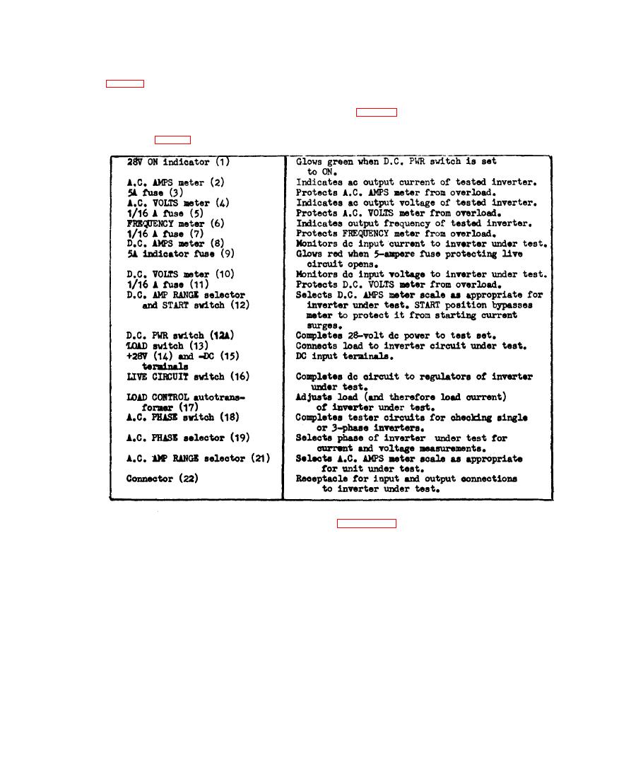
1-21 CONTROLS AND FUNCTIONS
FUNCTION
CONTROL
1-22. Cable 8
i n figure 1-5. Use five AWG 12 cables,
1 - 2 3 . Cable 8 shown in figure l-5 and used
a t l e a s t 3 6 i n c h e s 1 , between connect-
t o test the PU-543/A inverter may not be
o r type AN 3106-36-6P (tester end) and
supplied with the tester. Fabricate cable
connector type AN 3106-24-20S (11-pin
8 in accordance with the schematic diagram
c o n n e c t o r to the PU-543/A.
