TM11-6125-256-34
b Frequency Regulation Circuit If the voltage regu-
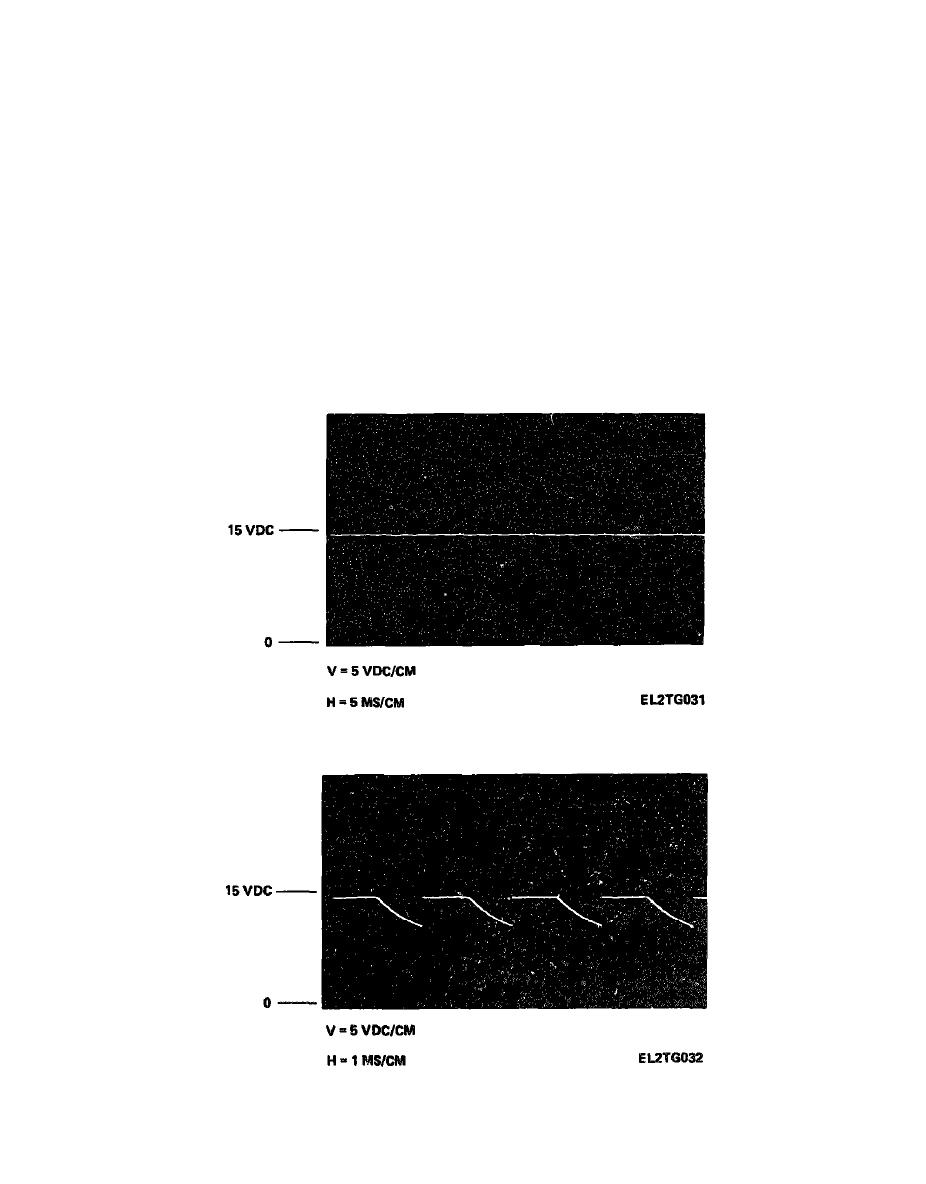
(1) Measure the voltage at the junction of re-
sistors R7 and R17 The voltage should be as shown
lation circuits are functioning properly, check frequency
in fig. 4-3 9 If the voltage is not as specified, check
regulation circuits as follows
diodes CR2 through CR5 for a faulty component.
(2) If the waveshape measured in step (1) indi-
NOTE
cates that diodes CR2 through CR5 are functioning
In the following voltage measurements, the
normally, make measurements at the base and collector
typical waveshapes given are for a normal
of transistor Q1 If the measurements are not approxi-
operating requlator During troubleshooting,
mately as shown in fig 4-3 10 localize the failure
while the frequency is incorrect (until the
within this circuit
problem is corrected), the measurements ob-
(3) If the waveshapes measured in step (2) indi-
tained will be similar to those shown, but at
cate that transistor Q1 and associated components are
a reduced amplitude When the problem is
functioning normally, measure the voltage across ca-
localized to a particular circuit, use fig FO-
pacitor C1 If the measurement is not approximately
2 1 as an aid in localizing the fault to a com-
as shown in fig 4-3 11 localize failure within this
circuit
ponent within this circuit


