
TM 9-6115-729-24
0003
DIGITAL VOLTAGE REGULATOR (DVR A3) MODULE OPERATION - Continued
CPU
The CPU contains the program which monitors generator output voltage and current, determines how much drive
current to supply the generator field in order to maintain desired output voltage, and monitors generator operation.
Alarm conditions are displayed on the digital display.
Voltage and Current Monitoring Circuits and Field Drive Circuits
The generator output is monitored for voltage and current. This data is input to the CPU where the data is
compared to the desired output from the generator. The field drive circuits provide field excitation current for the
generator, which regulates the output voltage of the generator.
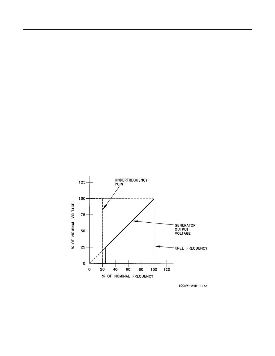
Startup Profile
The DVR operates under one of two operational profiles. When the DVR senses that the generator is starting to
produce voltage, the Startup profile is used. When the output frequency has increased above the knee frequency
(programmable), the DVR will switch over to the Loading and Stopping profile.
In the Startup Profile (Figure 11) the DVR will follow a 1:1 V/Hz profile after generator frequency (engine speed)
has increased above the under frequency point (parameter: 10). This profile continues until the frequency
reaches the knee frequency (parameter :06). Once the knee frequency has been reached, the generator will be
regulated by the DVR to produce full rated voltage, as set by parameter :01. The DVR then switches to the
loading and stopping profile.
