TM 9-6115-729-10
100 kW TACTICAL QUIET GENERATOR SET
0005 00
DESCRIPTION AND USE OF OPERATOR CONTROLS AND INDICATORS Continued
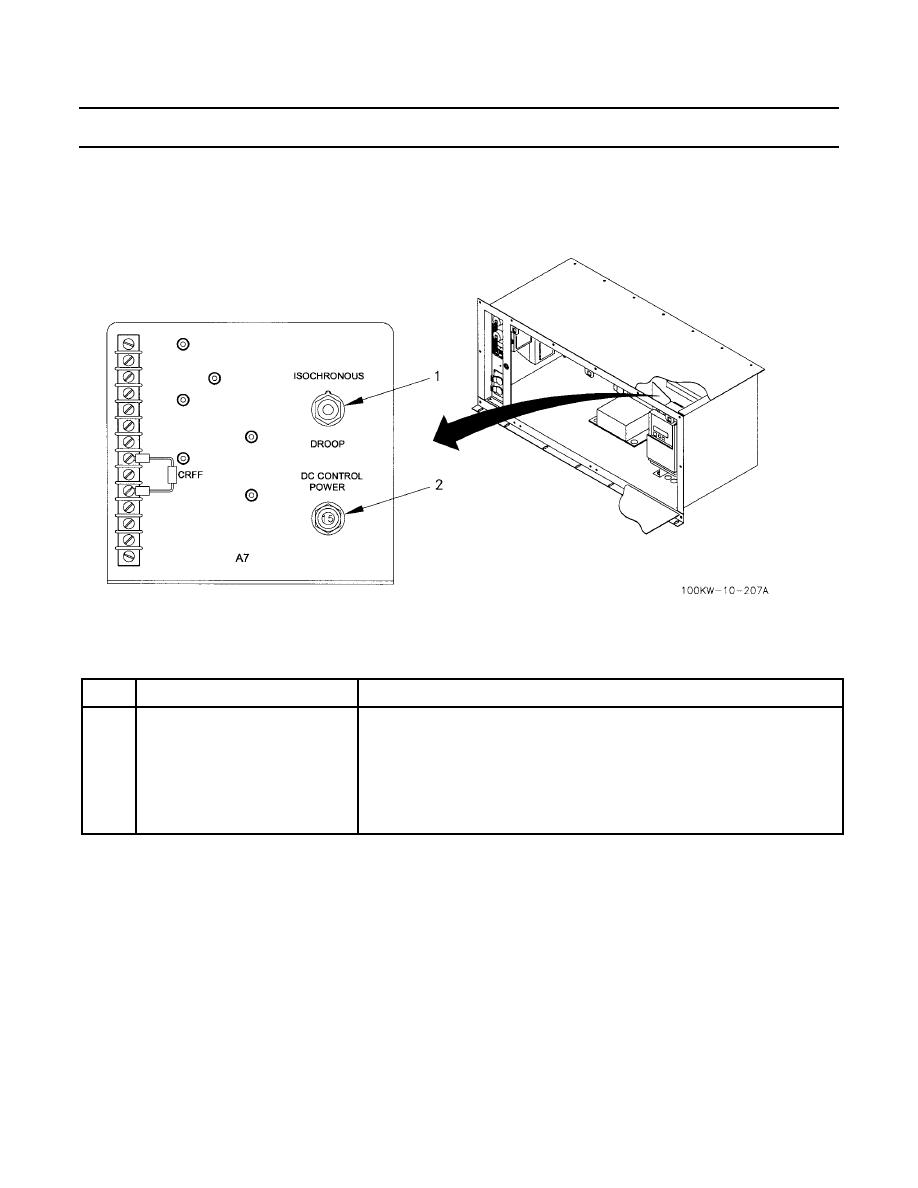
RESISTOR ASSEMBLY A7
Table 5 describes controls located on resistor assembly A7. Resistor assembly A7 is located inside the control box assembly
behind the EMCP.
Table 5. Resistor Assembly A7 Controls.
KEY
CONTROL OR INDICATOR
FUNCTION
1
ISOCHRONOUS/DROOP switch
Two-position switch. Used for frequency stabilization circuits and TQG
paralleling functions.
ISOCHRONOUS
Up position used for generator constant 50/60 Hz operation.
DROOP
Down position will accommodate fluctuations for under load conditions.
2
DC CONTROL POWER
When pushed in, circuit breaker supplies 24 Vdc power to GSC.
0005 00-12


