ARMY TM 9-6115-672-14
AIR FORCE TO 35C2-3-444-32
MARINE CORPS TM 09244A/09245A-14
4-208
4.16
CIM CONFIGURATION SWITCH
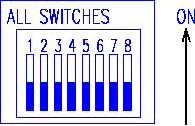
An eight position DIP Switch illustrated below is located beneath a protective plastic cover on the front of the
Computer Interface Module. This switch defines the configuration of the generator set for the Computer
Interface Module. The generator set configuration is defined in two ways: Output power (KW) rating, and
Frequency rating. This switch must be set to a specific configuration corresponding to the table below prior to
the module’s use in the generator set. Unless this switch is properly configured, the generator set can
experience a malfunction.
Configuration Switches Description:
There are eight rocker-type switches in one switch assembly, which is accessible from the front of the module.
Each switch is numbered left to right when viewing the module from the front. Each may be placed in either a
“up” (on) or “down” (off) position, which correspond to a logical “1” or “0” configuration.
SWITCH NUMBER
WHAT CONFIGURATION IS CONTROLLED BY THESE SWITCHES
1- 4
Power rating (30, 60 KW)
5
Frequency (50/60 or 400 Hz)
6-8
Not assigned.
The switch positions applicable to the 60 KW TQG sets are as follows:
Input/Output Module, Model TCM100:
SWITCH
1
2
3
4
5
6
7
8
GEN SET TYPE
Setting
off
on
off
off
off
off
off
off
60 KW, 50/60 Hz MEP-806B
Input/Output Module, Model TCM400:
SWITCH
1
2
3
4
5
6
7
8
GEN SET TYPE
Setting
off
on
off
off
on
off
off
off
60 KW, 400 Hz MEP-816B


