ARMY TM 9-6115-671-14
AIR FORCE TO 35C2-3-446-32
MARINE CORPS TM 09249A/09246A-14
5-60
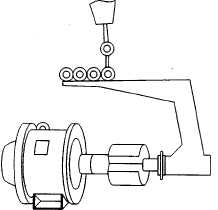
FIGURE 5-12. ROTOR ASSEMBLY LIFTING DEVICE (TYPICAL)
NOTE
Make sure all disc mounting holes at the inner and outer diameter are properly
aligned.
(7)
Install drive discs (22), washers (21), and bolts (20) on drive hub (26). Torque bolts (20) to 35
ft-lb (47 Nm).
(8)
Install generator assembly, paragraph 5.10.1.
5.10.7 Generator Main Stator and Housing,
a. Testing.
(1)
Shut down generator set, paragraph 2.11.2. Allow generator to cool to ambient temperature.
(2)
Open BATTERY ACCESS door (Figure 1-2), and disconnect negative battery cable.
(3)
Remove rear housing, paragraph 4.7.5.
(4)
Remove voltage reconnection terminal board. Refer to paragraph 5.8.2.
(5)
Tag and disconnect wires from voltage reconnection terminal, paragraph 5.8.
(6)
Connect resistance bridge, and note readings between terminals T1 and T4, T2 and T5, T3 and
T6, T7 and T0, T8 and T0, and T9 and T0 of voltage reconnection terminal board. Refer to FO-
1.
(7)
All resistance readings should be as shown in Table 5-2.
(8)
If resistance is low, there are shorted windings. If resistance is high, stator windings are open.
In either case, stator must be replaced.
(9)
Set multimeter for ohms, and connect between each of the ten coil leads from generator clamp
assembly (3, Figure 5-9) and ground.