ARMY TM 9-6115-670-14&P
4-100
4.38. GLOW PLUG.
This task covers:
a. Test
b. Replace
INITIAL SETUP
Tools
General Mechanic's Tool Kit
(Item 1, Appendix B)
Multimeter
Torque Wrench
(Item 2, Appendix B)
Shop Equipment, Electrical Repair,
Semi trailer Mounted
(Item 3, Appendix B)
Equipment Conditions
MASTER ON-OFF switch on APU control unit set to
OFF.
Engine stopped and allowed to cool completely.
Materials/Parts
Engine Glow Plugs
Manifold Glow Plug
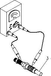
TEST
a. Remove glow plugs (perform steps a through f of REPLACE procedure).
b. Measure resistance across glow plug terminal and glow plugs and ground. Resistance should be
between 4.9 and 5.2 ohms.
c. If 0 ohm is indicated, there is a short between the terminal of the glow plug and the housing.
Replace the glow plug.
Figure 4-26. Glow Plug (Sheet 1 of 2)