TM 9-6115-669-13&P
2.1.3 Receptacles.
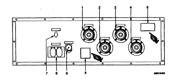
Control cabinet assembly receptacles are illustrated in figure 2-3. Receptacle functions are described
in table 2-3. J3 SLAVE RECEPTACLE 24 VOLTS on the base frame assembly is illustrated in
figure 2-4.
Figure 2-3 Control Cabinet Assembly, Receptacles.
Table 2-3 Control Cabinet Assembly, Description of Receptacles.
Item
Number
Description
Function
1
L1 (0A) receptacle with interlock
Connection to EPP III, PDU power cable
switch
2
L2 (0B) receptacle with interlock
Connection to EPP III, PDU power cable
switch
3
L3 (0C) receptacle with interlock
Connection to EPP III, PDU power cable
switch
4
N receptacle with interlock switch
Connection to EPP III, PDU power cable
5
J9 PARALLEL OPERATION recep-
Connection to EPP III, PDU control cable
tacle
6
J1/120 V 400 Hz double receptacle
Load connection (maximum 16 A)
7
J2/24 V receptacle
Load connection (maximum 6 A)
8
Warning Plate
Warning 208 VAC - Install protective covers
9
Warning Plate
Warning 208 VAC
2 - 1 0
Change 1


