TM 9-6115-664-13&P
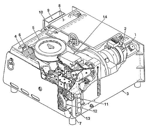
1. Twin Fan
2. Alternator
3. Air Inlet Duct
4. Air Inlet Hose
5. Engine Air Filter
6. Air Outlet Baffle
7. Thermostat
8. Engine Silencer
9. Exhaust Piping
10. Exhaust Cover
11. Engine Oil Cooler
12. Electric Fan
13. Air Outlet Baffle
14. Preheat Module
Figure 1-3. Cooling Air and Exhaust Components
t.
Diesel Engine. The APU is equipped with a four cycle, single cylinder, air cooled, fuel injected, horizontal
cylinder engine (Figure 1-4). It has a 95mm bore, a 100mm stroke, 709 cubic centimeter displacement, and has a rated
output of 15 horsepower at 3000 rpm. The engine fuel system consists of a solenoid (1), fuel injector assembly (2), fuel
injection pump (3), fuel feed pump (4), and associated fuel piping, hoses, and fittings.
u.
The engine oil system consists of an oil level dipstick (5), oil glow plug pipe (6), engine oil filter (7), oil pressure
valve (8), oil pressure switch (9), oil drain valve assembly (10), and oil filler (11). The engine is equipped with a 24 volt
starter motor (12) and an alternator assembly (13). A dry air filter assembly (14) is mounted to the top of the engine. A
speed control assembly (15) regulates engine rpm. A one piece flywheel housing (16) protects the engine flywheel and
covers the area of engine/alternator connection.
v.
Alternator. The APU uses a brushless, six phase, negative ground, externally energized, and selfrectifying
alternator (17, Figure 1-4). The alternator is supplied with an external, solid state regulator with flat temperature
compensation (18), a twin fan assembly (20), and fan guard (21).
w.
The engine and alternator are connected by a flexible rubber coupling and drive assembly. Four mounting feet
(22) and a mounting bracket (19) secure the assembled engine-alternator to the enclosure base.
1-7


