TM 9-6115-664-13&P
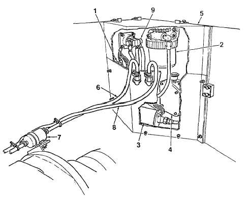
1. Fuel Fitting
2. Fuel Filter Water Separator
3. Electric Fuel Pump
4. Fuel Float Valve Assy
5. Fuel Module Cover
6. Fuel Supply Line
7. In-Line Fuel Filter
8. Fuel Return Line
9. NATO Receptacle
Figure 1-2. Fuel System Components
q.
Engine Cooling and Exhaust System. The engine cooling and exhaust system (Figure 1-3) draws cool air
into the APU for purposes of cooling the engine and alternator, and forces warm air and exhaust fumes from the
enclosure to the atmosphere. The cooling system consists of a twin fan (1) mounted to the alternator (2), an air inlet duct
(3) located in the base of the enclosure, engine air inlet hose (4), engine air filter (5), and engine air outlet baffle (6).
r.
The engine exhaust system consists of an engine muffler/silencer (8), mounted to the engine exhaust port, and
exhaust piping (9). An exhaust cover (10) attached to the side of the APU enclosure provides protection for the silencer
and exhaust piping. A rain cap on top of the exhaust piping prevents rain from entering. The cover is closed on the
bottom to ensure that all hot exhaust air escapes upward, and padded with sound-proofing material.
s.
An engine oil cooler (11) is mounted to the inside of the enclosure. An electric fan (12) is mounted directly in
front of the oil cooler and forces cool air across the oil cooler tubes. Warm air exits through a small air outlet baffle (13),
located on the side of the enclosure.
1-6


