ARMY TM 9-6115-645-24
AIR FORCE TO 35C2-3-444-12
MARINE CORPS TM 09244A/09245A-24/2
g.
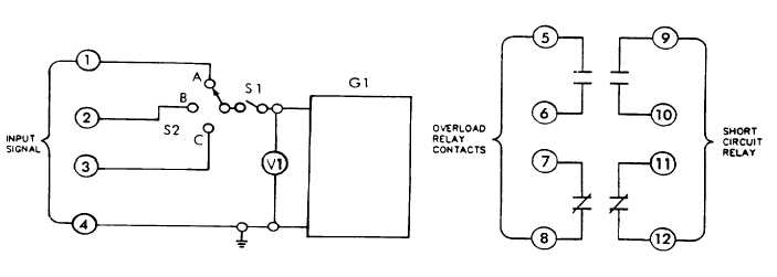
Set multimeter for ohms and check across terminals 5 and 6 while slowly increasing output voltage of G1 to
7.30 VAC (130% rated load). The relay should trip within 8 + 2 minutes. When relay trips, circuit 5 and 6
should close, circuit 7 and 8 should open.
h.
With multimeter still set on ohms, check across terminals 9 and 10. Slowly increase output voltage of G1,
when voltage reaches 23.9 ± 1.4 VAC the relay should trip. When relay trips circuit 9 and 10 should close
and circuit 11 and 12 should open.
i.
Return output voltage of G1 to O and open S1 allowing relay to reset.
j.
Place switch S2 in "B" position and close switch S1.
k.
Repeat steps f through i.
I.
Place switch S2 in "C" position and close switch S1.
m.
Repeat steps f through i.
n.
The voltages at which relay trips in positions A< B< and C should be within 1 volt.
o.
Replace any relay found to be defective.
p.
Install relay (paragraph 2-56-4).
FIGURE 4-1. Test Circuit
4-3
GOVERNOR CONTROL UNIT.
WARNING
High voltage Is produced when this generator set is In operation. Improper operation could result
In personal Injury or death.
4-3.1
Internal Crank Relay Test.
a. While holding the MASTER SWITCH (S-1) in the "START" position, check for voltage from pin positions 1, 3, 5
on the governor control unit (GCU) (A-5) to ground. The readings should be battery voltage. If there is no
voltage between any of the connections, the GCU (A-5) is not receiving the proper voltage and the wiring
harness should be checked. Refer to FO-1.
4-4 Change 2


