1-14
LUBRICATION SYSTEM.
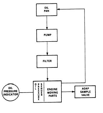
The Lubrication System
(FIGURE 1-6) consists of an oil
pan, dipstick, pump, oil
pressure sender, AOAP sample
valve, and filter. The oil pan
is a reservoir for engine
lubricating oil.
The dipstick
indicates oil level in the oil
pan.
A pump draws oil from the
oil pan and through a screen
removing large impurities. The
oil then passes through a spin-
on type filter where small
impurities are removed. From
the filter, oil enters the
engine and is distributed to the
engine’s internal moving parts.
After passing through the
engine, the oil returns to the
oil pan.
The OIL PRESSURE
indicator indicates oil pressure
sensed by the oil pressure
sender in the engine.
The
engine will shut off
automatically if the oil
pressure drops to a dangerously
low level.
The oil level can be
checked with engine running.
1-15
AIR INTAKE AND EXHAUST
SYSTEM .
1-15.1
The Air Intake and
Exhaust System (FIGURE 1-7),
consists of an air cleaner
assembly, intake manifold,
turbocharger,
exhaust manifold
and muffler.
Ambient air is
drawn into the air cleaner
assembly where it passes through
the air cleaner element.
Airborne dirt is removed and
trapped in the element. A
restriction indicator, located
on the air cleaner assembly
housing, displays red when the
air cleaner element should be
serviced.
Dirt can be removed
from the air cleaner housing by
pinching an evacuator valve.
ARMY TM 9-6115-645-10
AIR FORCE TO 35C2-3-444-11
MARINE CORPS TM 0924A/09245A-10/1
FIGURE 1-6.
Engine
System
Lubrication
Filtered air is drawn out of the
air cleaner assembly through air
intake tubes to the turbocharger
where it is forced into the
intake manifold to the combusion
chambers and mixed with fuel
from the injectors.
1-15