ARMY TM 9-6115-644-24
AIR FORCE TO 35C2-3-446-12
MARINE CORPS TM 09249A/09246A-24/2
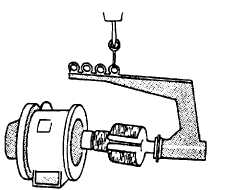
FIGURE 4-15. Rotor Assembly Lifting Device Typical)
e.
Attach a suitable rotor lifting device to drive hub (26) and overhead hoist as shown in FIGURE 4-15.
f.
Remove generator end bell, paragraph 4-19-1.
CAUTION
Special care should be taken when removing rotor assembly, winding damage could re-
sult if rotor is allowed to hit main stator.
g.
Carefully remove rotor assembly (28) and attached components from main stator and generator housing (11).
h. Remove main bearing, paragraph 4-19-1.
i.
Remove rotating rectifier, paragraph 4-20-1.
j.
Using bearing puller, remove drive hub (26) and key (27) from rotor assembly (28).
4-23-3 Installation.
a. Place key (27$ FIGURE 4-14) on rotor assembly (28) and install drive hub (26) over key (27) and onto main rotor
assembly (28).
b. Install rotating rectifier, paragraph 4-20-2,
c.
Install main bearing, paragraph 4-19-2.
CAUTION
Special care must be taken installing rotor assembly, winding damage could result if rotor
is allowed to hit main stator.
d. Attach a suitable rotor lifting device to drive hub (26) and overhead hoist as shown in FIGURE 4-15.
e. Carefully install rotor assembly (28) and attached components into main stator and generator housing (11).
f.
Install generator end bell, paragraph 4-19-2 and remove rotor lifting device.
g.
Install fan (25) on drive hub (26) with Iockwashers (24) and bolts (23).
4-43