ARMY TM 9-6115-644-24
AIR FORCE TO 35C2-3-446-12
MARINE CORPS TM 09249A/09246A-24/2
j.
Move AC CIRCUIT INTERRUPTER switch to CLOSED position and AC circuit interrupter relay should dose.
Move AC CIRCUIT INTERRUPTER switch to OPEN position and AC circuit interrupter relay should open. Ob-
serve AC CIRCUIT INTERRUPTER light for actuation of relay.
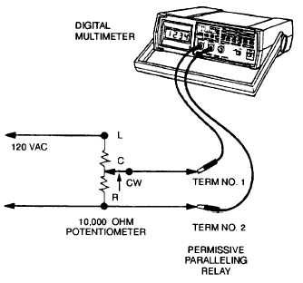
k. Adjust 10,000 ohm potentiometer clockwise until multimeter indicates 10 VAC.
FIGURE 2-15. Permissive Paralleling Relay Test Set-up
l.
Move AC CIRCUIT INTERRUPTER switch to CLOSED position. The AC circuit interrupter relay should not
dose (AC CIRCUIT INTERRUPTER light should remain dark).
m. Shut down generator set.
n. Disconnect negative battery cable.
o.
Replace permissive paralleling relay if operation is not as above.
p.
If no repair is needed, remove multimeter and test circuit wires. Reconnect wires 102D, 196A and 196B to per-
missive paralleling relay.
q. Raise and secure control panel.
r.
Connect negative battery cable and close battery access door.
2-57-3 Removal.
a.
Shut down generator set.
b. Open battery access door and disconnect negative battery cable.
c.
Release control panel by turning two fasteners and lower control panel slowly.
d. Tag and disconnect permissive paralleling relay (49, FIGURE 2-14) electrical leads.
e.
Remove screws (46) and permissive paralleling relay (49).
2-57-4
a. Install permissive paralleling relay (49, FIGURE 2-14) with screws (46).
2-93