ARMY TM 9-6115-641-24
AIR FORCE TO 35C2-3-456-12
2-36-2. Removal
a.
Shut down generator set.
b.
Open left side engine access door and disconnect negative battery cable.
c.
Remove control box top panel paragraph 2-16-1.
d.
Loosen rear outer ring and plastic insert from diagnostic connector (47, Figure 2-11).
e.
Tag and disconnect electrical leads from diagnostic connector (47) by inserting removal tool into pins of
connector.
f.
Remove screws (43) and nuts (44).
g.
Remove diagnostic connector (47) gasket (46) and cap (45).
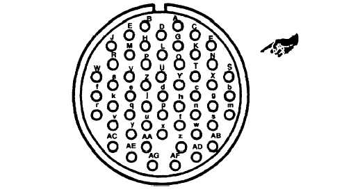
Figure 2-13. Diagnostic Connector Pin Positions (Front View)
2-36-3. Installation
a.
Install diagnostic connector (47, Figure 2-11) gasket (46) and cap (45) with screws (43) and nuts (44).
b.
Connect electrical leads and remove tags.
C.
Install control box top panel, paragraph 2-16-4.
d.
Connect negative battery cable and dose access door.
Change 2 2-65