
TM11-6125-256-34
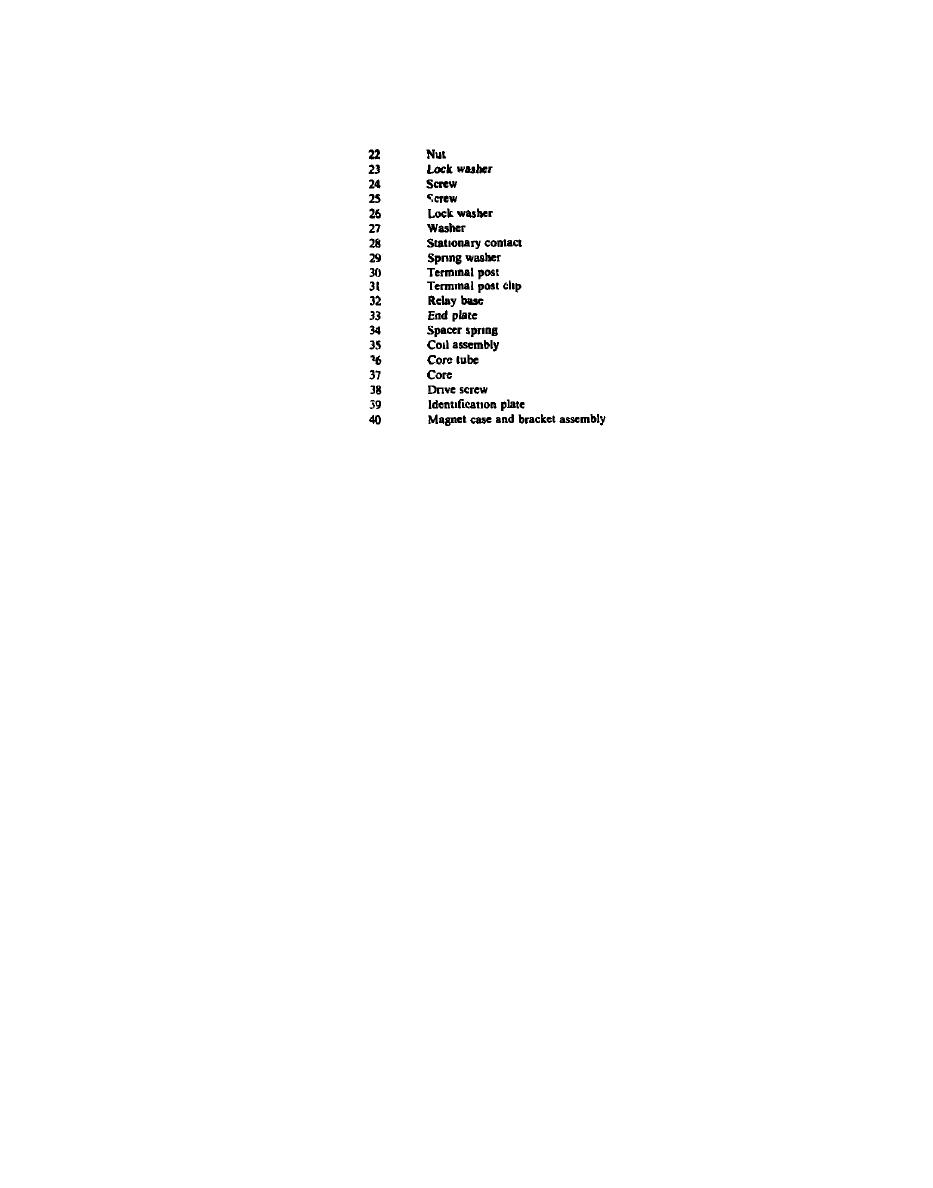
LEGEND FOR FIGURE 4-7 (Cont)
(3) Only if necessary for replacement, remove cable
(8) Remove end plate (33), spacer spring (34), and
assembly with terminals (5)
coil assembly (35) from magnet case and bracket
assembly (40)
f
AC End Bell Assembly (fig 4-9)
(9) Do not disassemble current relay assembly
further unless parts replacement is necessary
(1) Inspect inside diameter of bearing liner (16) If
the liner is worn, the motor-generator should be
forwarded to the depot for repair
e DC End Bell Assembly (fig 4-8)
(2) If necessary for replacement, remove screws (1),
lock washers (2), washers (3), and ground leads
(1) Inspect inside diameter of bearing liner (23) If
containing terminals (4 and 5)
the liner is worn the motor-generator should be
forwarded to the depot for repair
g E l e c t r i c a l R o t a t i n g E q u i p m e n t Housing
(2) If lead assemblies (4) are damaged remove
Assembly Inspect the inside diameter of bearing liner
screws (1), lock washer (2), washers (3), and lead
(23, fig 4-10) If the liner is worn, the motor-generator
assemblies
should be forwarded to the depot for repair
4-26
