
TM11-6125-256-34
ASSEMBLY 4B93-1-A
ing voltage measurements as described in paragraph
4-10.1. Inspection
4-10 3
a Inspect printed wiring board (43, fig 4-5 1) for
signs of damage
b Inspect wiring for loose or broken connections
Fig 4-3 1 shows the wiring connections for the volt-
age and frequency regulator assembly
c Check variable resistors R5 and R23 (13 and 1,
fig 4-5 1) and heat-sink mounted transistors Q6 and
Q11 (17) for signs of overheating or other damage
and Frequency Regulator Assembly
a Install the voltage and frequency regulator assem-
bly in a known good motor-generator PU-750A/A as
described in paragraph 3-14b
b Connect the motor-generator for testing as de-
scribed in table 3-4, using an input voltage of 28 volts
dc and no load on the generator If the motor speed is
voltage frequency regulator assembly 4B93-1-A
in excess of the 400-Hz speed to a point where the
motor attempts to run away, turn off power and per-
(3) Rotate the frequency adjustment potentiom-
form the following procedure
eter fully counterclockwise and then fully clockwise
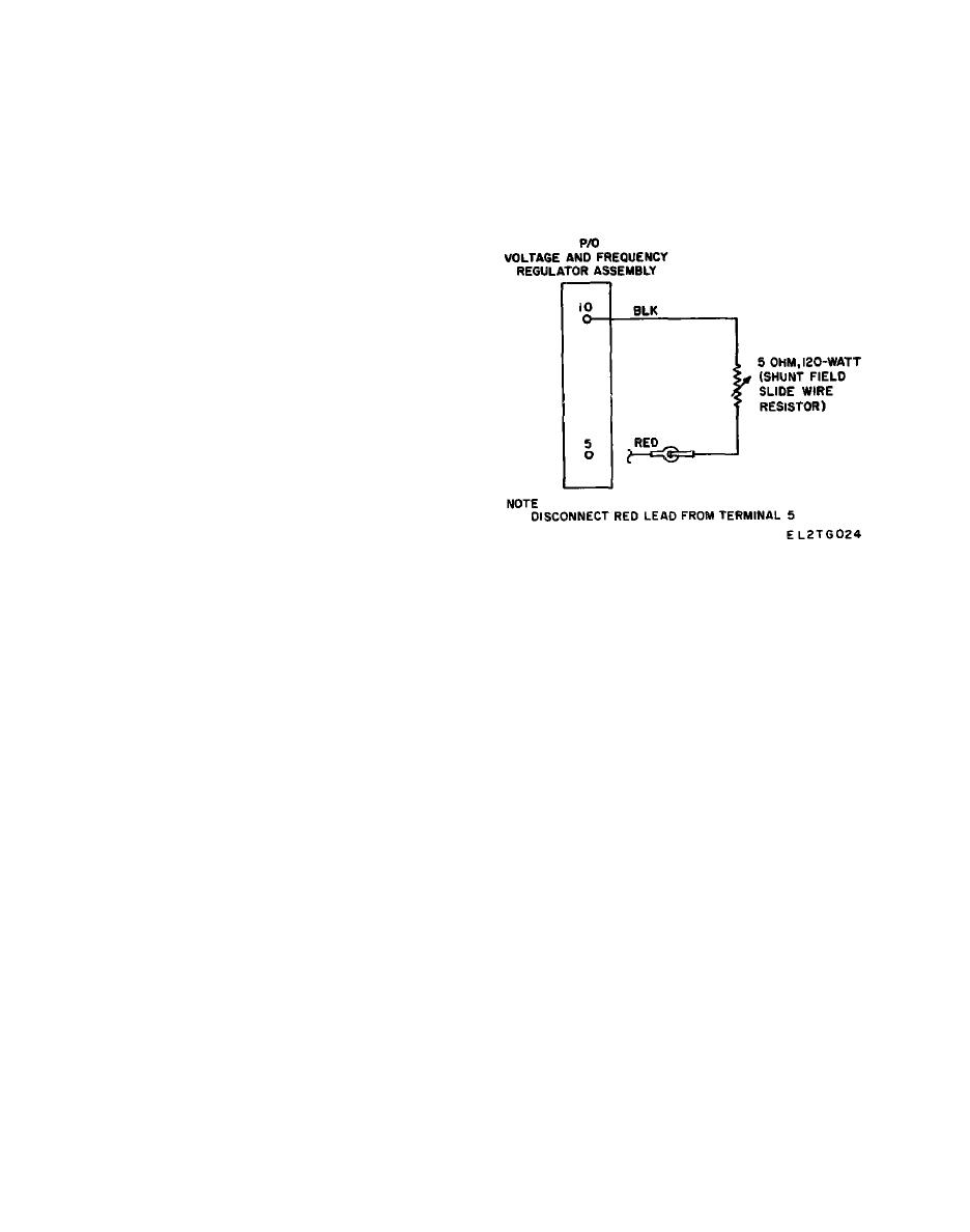
(1) Connect the shunt field slide wire resistor
while observing the phase A to neutral output fre-
as shown in fig 4-3 2
quency and voltage If the output frequency can be
(2) connect terminals 5 and 10 of the voltage and
varied between the limits of 390 and 410 Hz while the
frequency regulator assembly to ground through a 3 0-
ac output remains approximately 116 volts, the fre-
ohm, 300-watt resistor (This resistor will place a shunt
quency regulation circuits are probably operational
field load on the regulator)
However, to prevent an assembly with an intermittent
(3) Reapply the 28-volt dc input and adjust the
problem from being returned to service, subject the
shunt field wire resistor for a 400-Hz output
known good motor-generator with the questionable reg-
ulator assembly to general support commutation and
c Check that the following regulator input voltages
spin tests If these tests are satisfactorily performed, the
are present
assembly may be returned to service If incorrect re-
(1) At least 27 4 volts dc across the armature,
sults are obtained, make troubleshooting voltage meas-
measured at terminal 4 to ground
urements as described in paragraph 4-10 3
(2) 115 to 117 volts ac from terminal 1 to ground
(residual magnetic buildup voltage)
d To ensure that an operational voltage and fre-
Measurements
quency regulator assembly has not been returned for
A pointed probe will be required to puncture the pro-
General Support Maintenance, make the following
tective coating when making voltage checks After re-
check
pairs are completed, this coating must be restored in
(1) Reduce the dc input to 27 5 volts
accordance with paragraph 4-10 5, step e
(2) While observing the phase A to neutral out-
put voltage, rotate the voltage adjust potentiometer (fig
NOTE
3-1) fully counter-clockwise and then fully clockwise
All measurements are to be made with a 28-
If the output voltage can be varied between the limits
volt dc input and a 115-volt 400-Hz ac no-
of 110 and 120 volts, the voltage regulator circuits are
load output
probably operational If the output voltage range is ob-
a Voltage Regulation Circuits Check the voltage
tained, adjust the output to 116 volts and perform step
(3) If the range is not obtained, make troubleshoot-
regulation circuits as follows
