
TM11-6125-256-34
Section III. REPAIR OF VOLTAGE AND FREQUENCY REGULATOR
ASSEMBLY 4B48-6-A
assembly in known good motor-generator Pu-750( )/A
4-6. Inspection
as described in paragraph 3-11b
(fig. 4-5)
a Inspect printed circuit board subassembly (29, fig
b Connect the motor-generator for testing as
4-5) for signs of damage
described in table 3-4, using an input voltage of 28 volts
dc and no load on the generator If the motor speed is in
b Inspect wiring harness (61) leads for breaks and for
excess of the 400-Hz speed to a point where the motor
loose or broken connections Fig. 4-3 shows the wiring
attempts to run away, turn off power and perform the
connections for the voltage and frequency regulator
following procedure
assembly
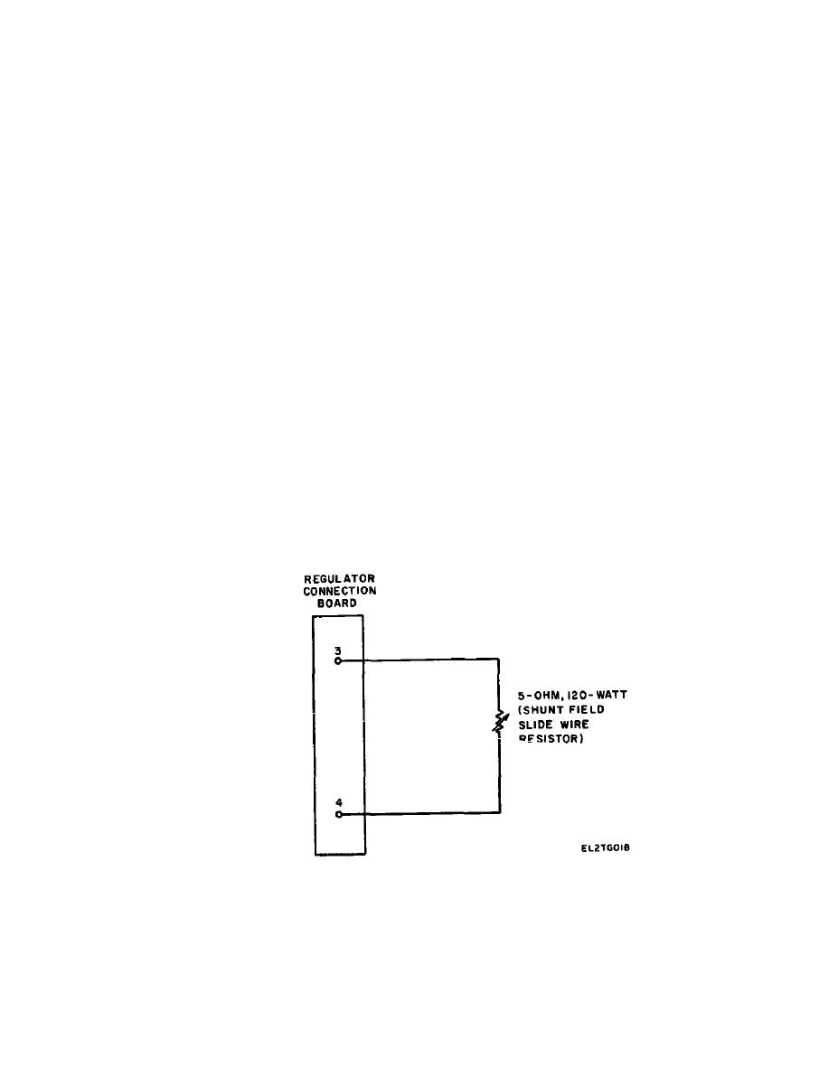
(1) Connect the shunt field slide wire resistor as
c Check adjustable resistors R14 and R15 (14 and 15,
shown in fig. 4-2
fig 4-5), fixed resistors R12 and R3 (20), and heat-sink
mounted transistors Q3 through Q6 (11 and 12) for signs
(2) Connect the frequency regulator lead
of overheating or other damage
disconnected from the regulator connection board to
ground through a 30-ohm 300-watt resistor (This
resistor will place a shunt field load on the regulator)
Test Setup for Troubleshooting Voltage
and Frequency Regulator Assembly
(3) Reapply the 28-volt dc input and adjust the
shunt field slide wire resistor for a 400-Hz output
a Install the voltage and frequency regulator
regulator assembly 4B48-6-A.
