
TM
11-6125-240-12
CHAPTER 2
INSTALLATION AND OPERATION
Section I. SERVICE UPON RECEIPT
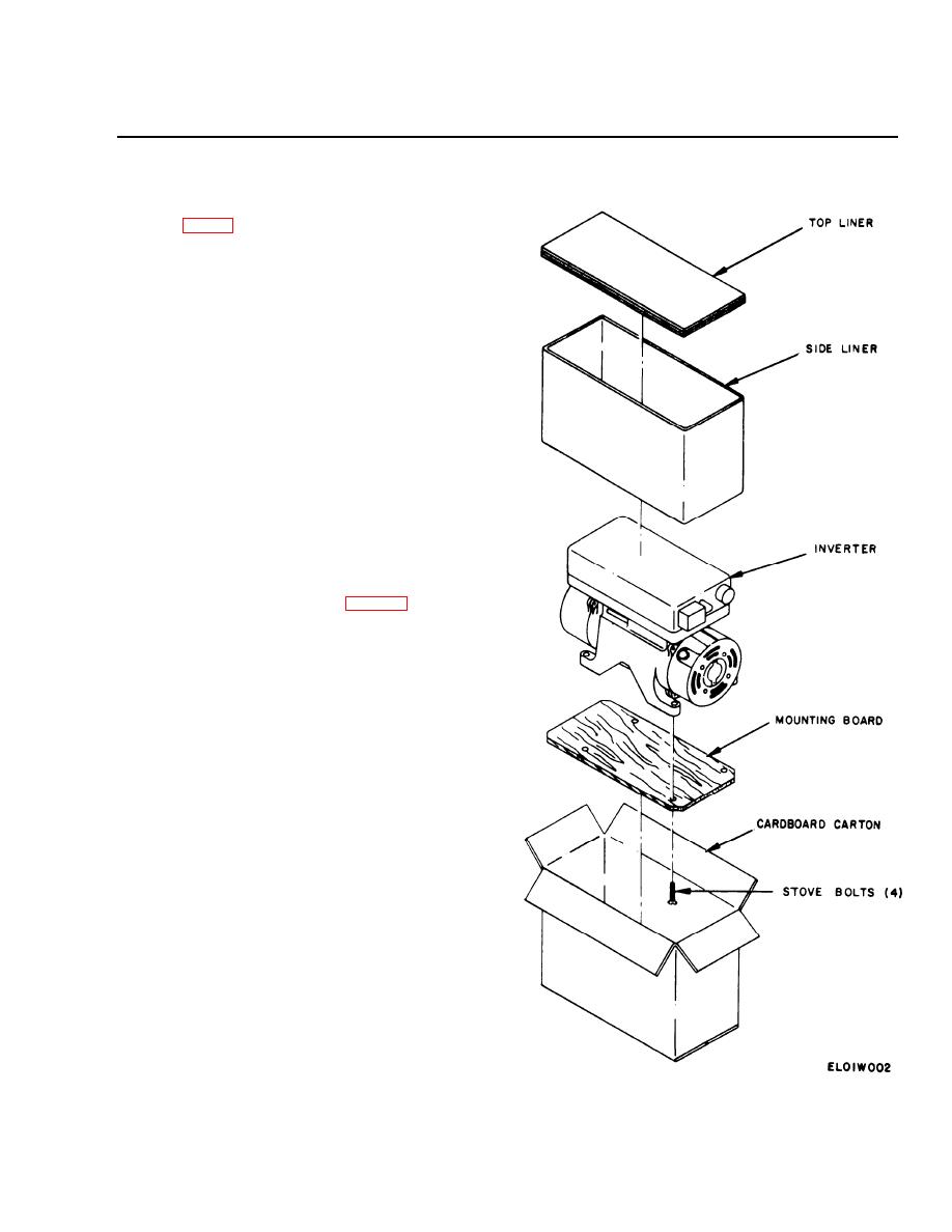
2-1. Unpacking
a. Packaging Data. When packed for shipment, the
PU-54S/A is mounted on a board and placed in a card-
board carton. It is further protected with a side and top
liner. The inverter consists of a single unit that is 9.5
inches high, 13.6 inches deep, and 7.1 inches wide,
weighing 45 pounds.
b. Removing Contents. Perform the steps outlined
below when unpacking the equipment.
(1) Open the cardboard carton.
(2) Remove the top and side liners.
(3) Lift the inverter and mounting base from the
cardboard carton.
(4) Remove the four stove bolts that attach the in-
verter to the mounting board and remove the inverter.
2-2. Checking Unpacked Equipment
a. Inspect the equipment for damage incurred dur-
ing shipment. If the equipment has been damaged,
report the damage on DD Form 6 (para 1-2).
b. Check to see whether the equipment has been
modified. (Equipment which has been modified will
have the MWO number on the front panel, near the
nomenclature plate.) Check also to see whether all cur-
rently applicable MWO have been applied. (Current
MWO applicable to the equipment are listed in DA
PaM 310-7).
2-3. Installation
The output and input power of the PU-545/A is routed
through the circuits of the aircraft in which the inverter
is installed. Refer to the applicable aircraft technical
manual for the desired mode of operation and physical
location within the aircraft, and to the following table
for the proper output connections at the ac power con-
nector. A typical installation procedure is presented in a
below.
Output
Ac Volts
Connection
115 single phase. . . . . . . . . . . . . . . . . . . . . . . . A-B
115 three phase. . . . A to F, B to G, and . . . . . A-B-C
C to D (delta)
110/208 three phase D, E, and F to C (wye). . . A-B (208 Vac) and
C-G(ll0Vac)
A-C (208 Vat) and
BG(ll0 Vac), or
B-C (208 Vac) and
A-C(ll0 Vac)
Figure 2-1.Packing diagram, PU-545/A
2-1
