
TB 9-6115-641-13
36. Drill a 1-1/8" diameter hole in rear of front housing (1), Figure 5-8.
37. Install other end of exhaust hose (15), into hole provided in rear of front housing (1). Use sealant provided in kit, around
hose and hole to prevent movement. Bend excess hose 90 to the right into front side of housing.
38. Drill a 7/32" diameter hole in the left side fan guard (14).
39. Secure exhaust hose (15) to fan guard (14), using clamp (12), screw (13), flat washer (11), lock washer (10), and nut (9).
40. Install butt splice (6), Figure 5-2, to heater fuel intake (10) using clamp (5). Bend item (10) to approximately 90 (only if
it interferes or touches the door when closed) making sure not to kink the metal tube so it pinches off the fuel supply.
NOTE
Route fuel hose, tubing away from exhaust system.
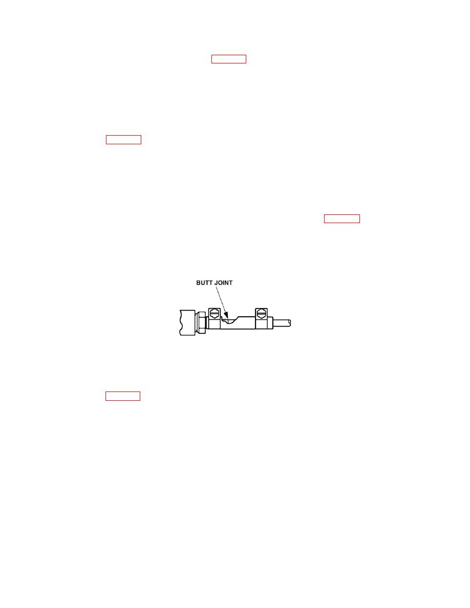
NOTE
When assembling fuel component parts together or fuel component parts to tubing, Figure 5-9, the
proper connection is a butt joint.
41. Install butt splice (6), Figure 5-2, to fuel pump (8) using clamps (5). Install tubing (9), from butt splice (6) on heater fuel
intake to butt splice (6) on fuel pump using clamps (5).
42. Attach butt splices (12) to fuel pump and to adapter (4), using clamps (11).
43. Install tubing (7), between butt splices (12) from fuel pump to adapter (4), using clamps (11).
44. Open storage box door.
