ARMY TM 9-6115-671-14
AIR FORCE TO 35C2-3-446-32
MARINE CORPS TM 09249A/09246A-14
G-22
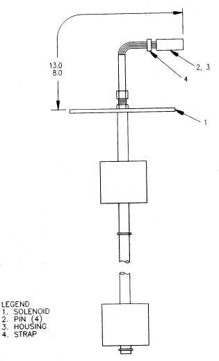
NOTES:
1. Dimensions are in inches.
2. Refer to TM 9-6115-671-24P for materials required.
PROCEDURES:
1. Strip 0.125 inch of insulation from end of each switch (1) lead.
2. Crimp pin (2) on end of each lead.
3. Insert pins into housing (3) with lead A in position 1, lead B in position 2, lead C in position 3, and lead D in
position 4.
4. Mark "P12" on strap (4), and install in position shown.
Figure G-21. Switch Assembly (P/N 88-22548)