ARMY TM 9-6115-671-14
AIR FORCE TO 35C2-3-446-32
MARINE CORPS TM 09249A/09246A-14
4-15
TABLE 4-4. UNIT TROUBLESHOOTING (CONTINUED)
OK
OK
Not OK
OK
OK
OK
Not OK
Yes
No
Not OK
OK
Notify next higher level
of maintenance.
No
Not OK
Not OK
No
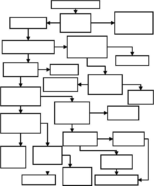
ENGINE CRANKS, BUT FAILS TO START
Engine cranks, but fails to start.
Pull EMERGENCY
STOP switch out.
Check FAULT
INDICATOR on
CIM display screen.
Is a fault displayed?
Go to troubleshooting
section corresponding to
fault displayed. See
Symptom Index, page 4-10.
Check EMERGENCY
STOP switch.(3, Fig
2-1) Is it pressed in?
Check Speed Control Unit DC
POWER LED.(15 Fig 2-3) Is it lit?
Check I/O interface module
(Fig 2-3) for 24VDC at
connector P25 pin 9. See
Wiring Diagram, FO-3.
No
Check the I/O interface
module (Fig 2-3) for
24VDC at connector P25
pin 8. Refer to Wiring
Diagram, FO-3.
Check EMERGENCY
STOP switch circuit for
broken wires or connections.
See Schematic, FO-1.
Repair broken
wires and
connections as
necessary.
Replace I/O interface
module (see para.
4.8.25).
Check Speed Control
Unit connections. See
Wiring Diagram, FO-3.
Replace DCS speed
control unit (see para.
4.8.22).
Replace backplane
module (see para.
4.8.24).
Does SPEED SENSOR
LED (12, Fig 2-3) on Speed
Control Unit illuminate
during cranking?
Inspect magnetic pickup
(see para. 4.13.3). Are
there broken wires or
loose connections?
Repair or replace wires.
See Wiring Diagram,
FO-3.
Replace magnetic
pickup (see para.
4.13.3).
Repeat Starting procedure
(Para 2.11.1).
Test Emergency
Stop Switch
(3, fig 2-1)
Ref Para 4.8.14.
Replace Emergency
Stop Switch (3, fig
2-1) Ref Para
4.8.14.
Yes
Yes
Yes
Continued on next page
Yes
Notify next higher level of
maintenance.
No


