TM 9-6115-648-14&P
CHAPTER 5
DIRECT SUPPORT AND GENERAL SUPPORT
MAINTENANCE INSTRUCTIONS
Section I. INTRODUCTION
5-1. General. This chapter contains direct support and general support level maintenance procedures for
components of the M200A1 trailer added when the trailer is used as part of the PU-650B/G power unit. These
components are not covered in the overall trailer maintenance manual. For all other direct and general support
maintenance procedures on the trailer, refer to TM 9-2330-205-14&P. For direct and general support
maintenance procedures on the generator set, refer to TM 5-6115-545-34.
WARNING
Before performing any maintenance that requires climbing on or under trailer, set trailer
handbrakes, chock wheels and lower rear leveling jacks. Injury to personnel could result
from trailer suddenly rolling or tipping.
Section Il. MAINTENANCE OF POWER UNIT TRAILER
5-2. Step and Fender Repair. Repair of the front and rear steps and the fenders is limited to straightening,
welding and repainting. If required, repaint in accordance with MIL-T-704, Type F, Color Green, No. 383 of
MIL-C-46168. If power unit is painted in camouflage, refer to paragraph 5-4, Marking.
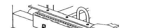
5-3. Accessory Box Repair. (See figure 5-1.) The accessory box is repaired by replacing the latch and
strike assemblies. The box itself may be straightened, welded and repainted. If required, repaint in accordance
with MIL-T-704, Type F, Color Green, No. 383 of MIL-C-46168. If power unit is painted in camoufIage, refer to
paragraph 5-4, Marking. Replace latch and strike assemblies as follows:
a.
b.
c.
Grind off or drill out solid rivets (1, figure 5-1) securing latch and strike assembly (2) to accessory box (3).
Position new latch and strike assembly (2) on accessory box (3) and secure with solid rivets (1).
Touch up with paint as required.
Figure 5-1. Accessory Box Repair.
5-1