TM 9-6150-226-13
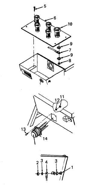
4-21 MOUNTING BOARD AND INPUT CONNECTOR.
(cont)
2.
c.
Tag wires (7) according to
the load terminal connection.
Remove nuts (8) and washers (9)
and disconnect wires from
bottom of load terminals (10).
d.
Remove nuts (11), washers (12),
and screws (13) securing input
connector (14) to box and
remove connector.
INSTALL CONNECTOR.
a.
Insert input connector (14)
through front of box and
secure with nuts (11),
washers (12), and screws (13).
b.
c.
d.
Connect wires (7) to bottom
of load terminals (10).
Secure with nuts (8) and
washers (9) and remove tags.
Position terminal board (6)
inside universal adapter box.
Secure terminal board (6)
with bolts (5).
FOLLOW-ON MAINTENANCE:
Connect lanyards (para. 4-14).
TEST
WARNING
High voltage is present in this system. DISE and
PDISE supports equipment using 120/208 V ac. Do
not attempt continuity check with the power on.
Death or serious injury may result.
TEST CONNECTOR.
Perform a continuity test in accordance with Table 4-7.
4-60