
TM 9-6115-730-24
0100
INSTALLATION - Continued
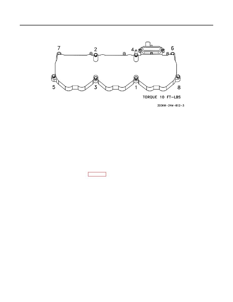
Figure 1. Valve Cover and Base (Sheet 3 of 3).
3. Using the illustrated sequence (Figure 1, Sheet 3), torque bolts (Figure 1, Sheet 2, Item 15) to 7-11 lb-ft (9-15
Nm).
4. Install three valve covers (Figure 1, Sheet 2, Item 14), 18 washers (Figure 1, Sheet 2, Item 13), and bolts
(Figure 1, Sheet 2, Item 12). Using the illustrated sequence, torque bolts (Figure 1, Sheet 2, Item 12) to 7-11
lb-ft (9-15 Nm), then re-tighten, using the same sequence, to 7-11 lb-ft (9-15 Nm).
5. Install gasket (Figure 1, Sheet 2, Item 11), breather (Figure 1, Sheet 2, Item 10), four washers (Figure 1,
Sheet 2, Item 9), and bolts (Figure 1, Sheet 2, Item 8).
6. Install atmospheric pressure sensor (WP 0098).
7. Install hose (Figure 1, Sheet 1, Item 7) to the side of the valve cover base and tighten clamp (Figure 1, Sheet
1, Item 6).
8. Install clamp (Figure 1, Sheet 1, Item 3) and harness assembly (Figure 1, Sheet 1, Item 5).
9. Install the bolt (Figure 1, Sheet 1, Item 1) and washer (Figure 1, Sheet 1, Item 2) that holds the clamp (Figure
1, Sheet 1, Item 3) for the harness assembly to the valve cover base (Figure 1, Sheet 1, Item 4)
END OF TASK
END OF WORK PACKAGE
0100-5/6 blank

