
TM 9-6115-729-24
0115
VALVE LASH ADJUSTMENT
NOTE
Perform steps 1 thru 10 if No. 1 cylinder is on compression stroke.
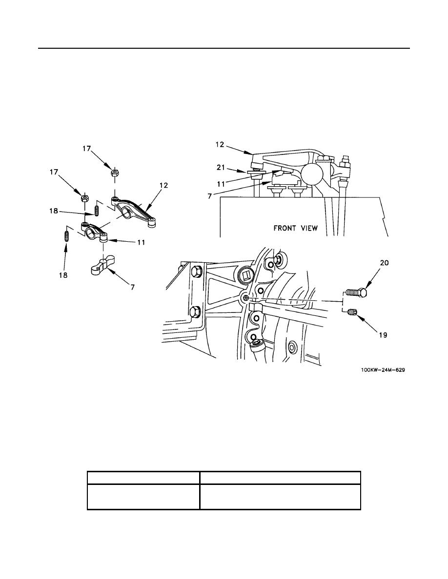
1. Loosen nut (Figure 3, Item 17) and loosen adjustment screw (Figure 3, Item 18) on inlet rocker arm (Figure 3,
Item 11) for cylinders 1, 2, and 4.
2. Refer to Table 3 and insert feeler gage of correct dimension between inlet rocker arm (Figure 3, Item 11) and
inlet bridge (Figure 3, Item 7).
3. Turn adjustment screw (Figure 3, Item 18) clockwise (CW) until inlet rocker arm (Figure 3, Item 11) is set to
specification in Table 3.
Valves
Gage Dimension
Inlet
0.015 in. (0.38 mm)
0.025 in. (0.64 mm)

