ARMY TM 9-6115-670-14&P
4-125
i. Install clevis (10) and turn until clevis (10) is up against stop nut (12).
j. Align hole in rod end bearing (5) with hole in clevis (10) and install socket head screw (11), lock
washer (9), and nut (8).
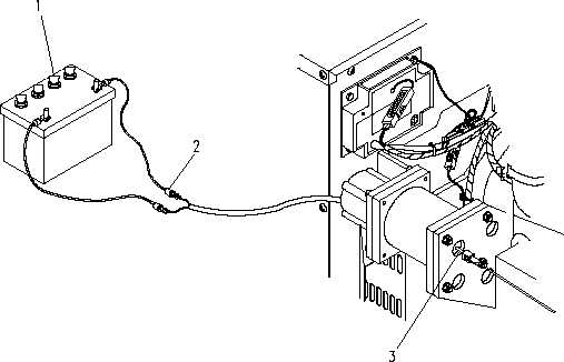
k. Reconnect actuator/solenoid leads (2) with electrical leads. Remove tags.
l. Adjust actuator linkage (para 4.50.).
Figure 4-37. Actuator/Solenoid (Sheet 1 of 2)
NOTE
Ensure that stop nut and clevis are completely threaded
on shaft. No threads should be visible.