4-3
h.
i .
j.
k.
l.
m.
n.
o.
p.
ARMY TM 9-6115-644-24
AIR FORCE TO 35C2-3-446-12
MARINE CORPS TM 09249A/09246A-24/2
With multimeter set on OHMS, check across terminals 9 and 10. Slowly increase output voltage of G1. When
voltage reaches 23.9 +/-1.4 VAC the relay should trip. When relay trips, circuit 9 and 10 should close and circuit
11 and 12 should open.
Return output voltage of G1 to 0 and open S1 allowing relay to reset.
Place switch S2 in “B” position and close switch S1.
Repeat steps f. through i.
Place switch S2 in “C” position and close switch S1.
Repeat steps f. through i.
The voltages at which relay trips in positions A. B, and C should be within 1 volt.
Replace any relay found to be defective.
Install relay, paragraph 2-56-4.
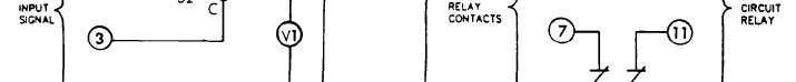
FIGURE 4-1. Test Circuit
GOVERNOR CONTROL UNIT.
High voltage is produced when this generator set is in operation. Improper operation
could result in personal injury or death.
4-3-1 Troubleshooting Procedures
a. While holding the Master Switch (S-1) in the “START” position, check for the voltage from pin positions 1,3,5
on the GCU (A-5) to Ground. The readings should be battery voltage. If there is no voltage between any of the
connections, the GCU (A-5) is not receiving the proper voltage and the wiring harness should be checked. Refer
to FO-1.
NOTE
With the generator running the voltage will read zero.
4-5