
Paragraph 4-11 to 4-15
required test values by rotating the LOAD CONTROL
autotransformer selector (17) to values stated for
the inverter.
4-12. Obtain voltage and current values of individ-
ual circuits and record as follows:
a. Three-phase inverter:
1. Set A.C. PHASE switch (18) to 30.
2. Selectively rotate A.C. PHASE selector (19)
indicator through engraved ranges 1, 2, and 3 (phase
recording).
3. Observe meter indications at each phase
point, and record.
b. Single-phase inverter:
1. Set A.C. PHASE switch (18) to 1.
2. Set A.C. Phase Selector (19) to Neutral
Position.
3. Observe Meter Indications and Record.
4-14. Test being completed, rotate the LOAD CON-
TROL autotransformer selector (figure 1-3, 17)
counterclockwise to 0%, and position toggle switches
LOAD (13), D.C. PWR (12A), and LIVE CIRCUIT (16)
to OFF.
4-15. Remove attached cable assembly and store
all cable assemblies in storage compartment. Cover
tester when not in use to protect equipment.
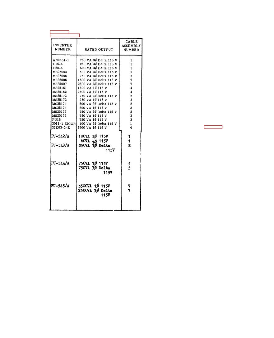
Number Selection List
placarded setting 5, and slowly increase test load to

